While working on my Statscreen project, I decided to add a photoresistor so that the brightness of the LCD’s backlight can be automatically adjusted based on ambient lighting. My first thought was to create a voltage divider and measure the voltage with the AVR’s ADC, but, after reviewing the project schematic, determined that I had no free ADC pins available. I would, therefore, need to create a resistor-capacitor (RC) network and measure the time to charge the capacitor through the resistor (photocell). After spending several hours on the circuit and firmware, I had a working implementation- only to discover that I did, in fact, have an ADC pin available! I remember reading about RC timing in an old Parallax STAMP book, but couldn’t find much on the Web about how to implement one on an AVR (presumably because it’s easier and more accurate just to use an ADC these days). So while this technique probably isn’t all that useful, I thought I’d share what I learned, if only for my own future reference.
Theory
RC circuits are one of the basic electrical concepts that were taught in my college curriculum. Simply put, the length of time required to charge a capacitor C to a certain voltage V(t) through a resistor R is related to the resistance and the capacitance as:

Solving for t,

In short, larger capacitance and greater resistance increases the charge time. With a known capacitance and voltage, we can then determine R by measuring the time required to charge the capacitor to a given voltage. In the case of a microcontroller circuit, that voltage will be the low->high logic transition voltage (about 2.6 volts for the ATMega328p running at 5V).
Circuit
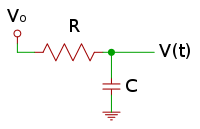
In the circuit above, we replace R with a CdS photoresistor, which decreases its resistance as light intensity increases. Connect Vo to the microcontroller’s input pin. Though I’ve omitted it for clarity, this pin should connected through another resistor, somewhere around 220 ohms.
The choice of capacitor is, in theory, irrelevant to determining R. In practice, however, we want to select a capacitance that will yield a charge time compatible with the capabilities of our microcontroller. Too small a capacitor, and it may charge too fast for the controller to register a count. Too large, and it may charge so slowly that the controller’s counting mechanism maxes out. Thus, in order to select an appropriate capacitor, we must first determine the microcontroller’s timing window. This is highly dependent on the system clock speed, size of the counter or timer (8/16/32-bit, etc.), and the efficiency of the code doing the timing. In the C code example below, I’m running a very simple loop that increments a 16-bit counter until it hits its maximum value or the transition voltage is reached. Because each iteration requires only a few processor cycles to complete, the counter will saturate very quickly at a typical 8 MHz AVR clock speed. But while a fast loop narrows the timing window, it also increases the precision of the count. So the ideal timing loop is one that “ticks” as fast as possible to maximize precision, but can also count to a very high number to lengthen the available timing window.
The other factor to consider when selecting the capacitor is the expected value of R that will be measured. In most applications, R be within a predictable range. A variable potentiometer, for example has a clearly defined range under all conditions. A photocell isn’t as well defined, but typical values can be determined by measuring its resistance with a multimeter under the lighting conditions in which it’s expected to operate.
Code
#define MAX_COUNT      50000
#define cds_pin_state  CDS_PIN & _BV(CDS_BIT)

unsigned int rc_time(void) {
  unsigned int count = 0;
  CDS_DDR |= _BV(CDS_BIT); //set output
  CDS_PORT &= ~_BV(CDS_BIT); //set low
  _delay_us(50); //give the voltage a chance to drop to zero
  CDS_DDR &= ~_BV(CDS_BIT);  //set input
  while(count < MAX_COUNT && cds_pin_state == 0) count++;
  return count;
}