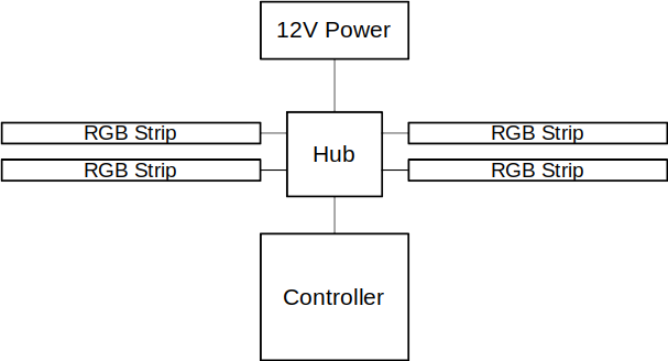
Having recently built up a new AMD Ryzen PC for fun and profit, I decided to dress it up with some case lighting. Off-the-shelf RGB is a dime a dozen nowadays. In fact, my Asus motherboard even includes onboard RGB strip headers for that very purpose. However, the quality of both the LED hardware and the vast, disparate ecosystem of software to control it all is typically very poor quality. I figured I could do better. Turns out, I had a set of Ikea light bars that I purchased some time ago on an impulse, and it’s actually a very nice little set. It consists of four RGB LED bars mounted in rigid plastic, each of which plugs in to a central power hub. A handheld, wired controller also plugs in to the hub. The controller is simple: two buttons for pre-programmed rainbow modes, and a dial for manual color selection. It’s all powered from a 12 VDC wall adapter. (Fig. 1)
The first step was to glue some small magnets to the back of each light strip for easy case mounting. I installed the strips in the case just to see how it would look, and the results were pretty good. Nothing special, but the lights nicely highlight the build.
Next, I chopped the power cable and spliced it on to the 12 V line of a Molex connector. No issues there- still works fine, and now it turns on and off with the computer. This, of course, led me to the main component of the build- the controller.
Initial requirements were set as follows:
- Software control (Python or C, probably) via internal USB header
- Full RGB and PWM-dimmable (The original controller only supported color selection, not total brightness)
- “Mirage” mode- pulse lights at a frequency that matches CPU or case fans, in order to produce an aliasing effect
- Complete project in 1-2 months, and maximize the use of parts on hand
Requirement 1 is pretty straightforward. Python is great for its simplicity and portability. However, I started working with example code in C, so that’s my starting point. The tricky part is getting a microcontroller to talk USB. I do not want to use a USB to serial conversion, but instead implement a native USB device in firmware. My initial thought was a Teensy, but I didn’t have one in my parts bin. More on that in a moment.
Requirement 2 should be easy to implement with discrete PWM channels for R, G, and B. This partly drives microcontroller selection.
Requirement 3 is based on a feature that came with the CoolerMaster Wraith cooler that comes bundled with the Ryzen 7. You can manually set the pulse frequency in software, but there’s no way to poll fan speed and automatically sync the lights with the fan. I did, however, work briefly on some Python code to poll fan speed and adjust the lights accordingly, using the pySensors and cm-rgb libraries. However, I actually just ended up replacing that CPU cooler altogether with a much quieter one from BeQuiet. Nevertheless, I should still be able to replicate the effect to some degree with case lighting, despite the lack of LEDs in the new CPU fan.
Finally- and this is most important- I want something I can actually handle. My projects tend to span years, due to my proclivity for biting off more that I can chew, being a perfectionist, falling victim to feature creep, and burnout. The percentage of projects I undertake that end up languishing unfinished for years and years is embarrassingly high.
Hardware
Microcontroller
As I mentioned, my initial thought was to get a Teensy, since I know they can easily handle a USB stack with plenty of room to spare in both speed and storage. However, I have no experience with that ecosystem, which would slow down the project. I remembered, though, that I had an extra Adafruit Pro Trinket left over from my USB-enabled Statscreen project from a few years ago. Since it worked (and continues to work) brilliantly for that project, it should be a snap to integrate it in to this one. And since the ATMega328p has three onboard timer/counters, each with two PWM outputs, I’ll be able to easily control all three LED channels.
LED Circuit
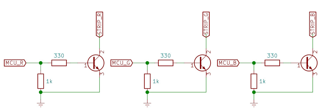
Obviously, I can’t power 108 LEDs (36 RGB modules) from a 5V IO pin. The LED strips have onboard limiting resistors, and are all powered by a common cathode tied to the 12V rail in the hub, so all that’s required is turn on one of the channels is to tie the anode to ground. This can be accomplished with a simple NPN circuit. I had a handful of 2N3904 NPN transistors (that I’m pretty sure I pinched from my college electronics lab a decade ago…), so I used those. However, I was concerned that powering all four LED strips might exceed the 200 mA limit of the 2N3904. Luckily, each of the three colors only consume a little over 100 mA. So no issues there. A few resistors are are the only other components required. See Fig. 2 below.
Power
This part is easy. I can get the 12V for the LED strips directly from the computer’s PSU, and 5V for the microcontroller over USB. If I needed to, I could even get the 5V from the PSU as well, but USB puts out 500 mA, which is plenty for this project.
Cables
This project requires three cables:
- Molex power cable
- Controller to hub cable
- Internal USB cable
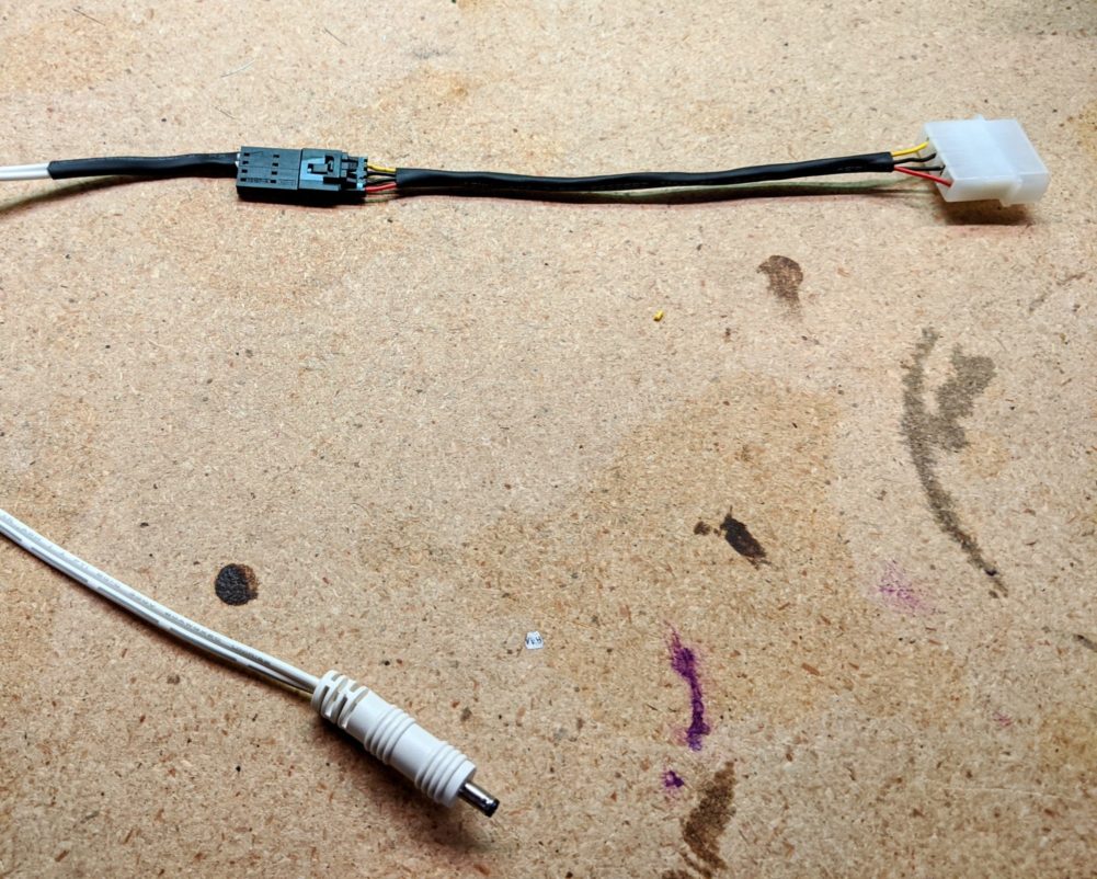
To make the power cable, I chopped a Molex connector off an old case fan, and soldered the light kit’s power cable leads on to the 12V lines.
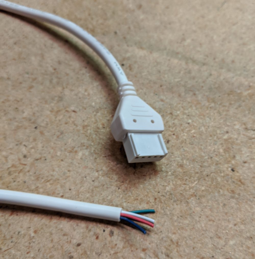
For the controller to hub cable, I cut the original controller interface cable (Fig. 2) and soldered the R, G, B, and gnd wires to my new controller board. Since the microcontroller is powered by USB, I didn’t need the 12V wire.
Firmware
Info coming soon
Software
Info coming soon
-
- Fig 1: Schematic diagram of the original light kit. My project primarily replaces the handheld controller with a software-controlled USB device.
-
- Fig. 2: LED-microcontroller interface circuit. Each of the three color channels are identical.
-
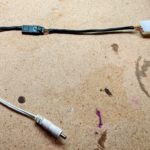
- Fig. 3: Molex power adapter. The barrel jack at the bottom plugs in to the light strip hub. Originally, it was attached to a 12VDC wall adapter.
-
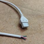
- Fig 4: Controller-hub cable. Much respect to Ikea for appropriately color-coding the red, green, and blue, and ground wires. The white wire is the unused 12V line.
-
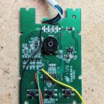
- I soldered lead wires on to the inputs of the red, green, and blue channel switching transistors, as well as 12V and ground. This allowed me to control each channel from the Trinket. I disabled the onboard MCU by bridging its ground and reset lines with a solder blob.
-
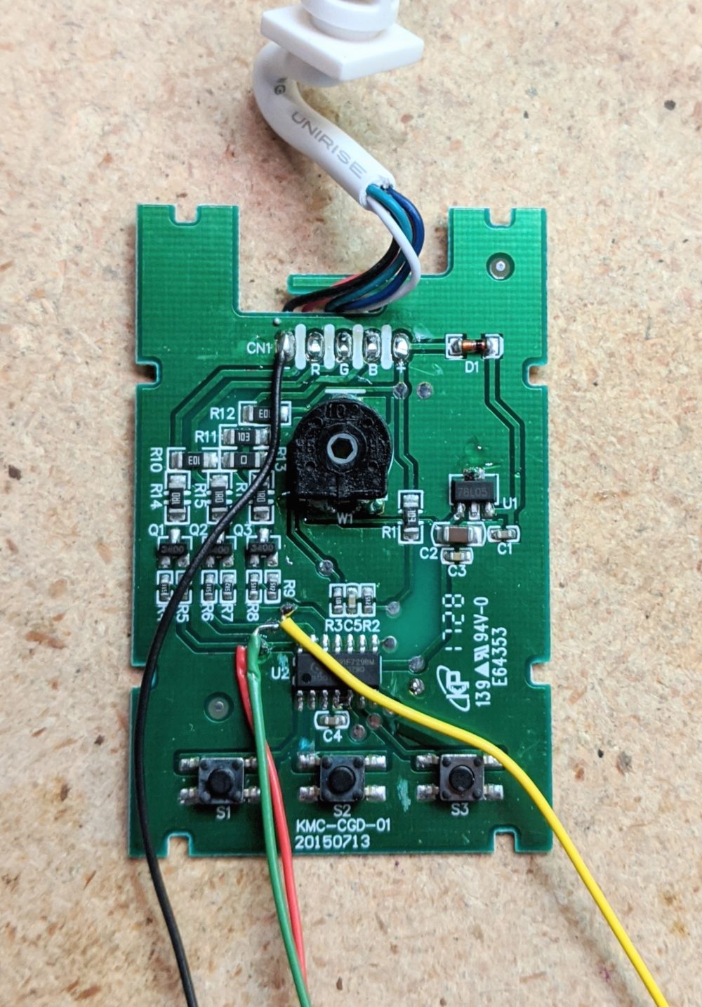
- Here’s the Trinket operating independently from the stock control board. NPN transistors switch each of the three channels via a 5V PWM signal from the Trinket.

-

- Please, spare me your judgements about the placement of my SoundBlaster directly beneath my RTX. It stays within thermal design limits! Step off!